
- Joined
- Nov 2, 2017
- Messages
- 8,975
- Likes
- 1,140
- Points
- 4,577
- Age
- 41
- Location
- Tbilisi
- Website
- alexlaptoprepair.com
PMBUS MPS PROGRAMMER
Features:
Support Online/Offline mode ( connect to motherboard directly , or in some cases we need to solder the ic on the offiline adapter )
All Requirements Support
3V,1.8V,SCL,SDA
EN/PE,IREF,IREF2,PGOOD,SALRT
ESD Protections , Indicators
Read & Write program
Monitor functions online and offline
Change parameters
Support backup one chip or all systems ( multi chip together )
PMBUS PROGRAMMER CHIP SUPPORT LIST:
MP2940, MP2940A, MP2940C, MP2942, MP2943
MP2944, MP2945,MP2948C MP2949A, MP2950
MP2959, MP2962, MP2969, MP2979A,MP2955
MP2956,MP2958, MP2951, MP2853, MP2888
MP2886,MP2884, MP2965,MP2966,MP2968
MP5023,MP2975,MP2978,MP2972, MP2855
MP2949A, MP5920, MP5922, MP2926, MP2988
MP2971,MP2973, MP2845,MP2845A, MP2856
MP2857, MP2880, MP2882,MP2872,MP2874
MP2878,MP2960, MP2964, MP9941, MP2985
MP2992,MP2993, MP2986,MP2983,MP2975,MP2972
MP2976,MP2978,MP2995,MP5990,MPQ2977
MPQ2967,MPQ2861MP2862,MPQ8646,MP2860
MP2891,MP2890,MP2891A

MPS Import & Export & Modify Program :
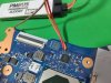


Connect the mps chip online using SCL,SDA,GND to the motherboard laptop , pc , gpu card
or solder your mps chip on the offline adapter and connect it to the programmer
Open the MPS software ( download link with the progammer ) , when it is not connected to the programmer, the following red message will showing [USB is not connected!
When the programmer is connected, the [USB is not connected!] will disappear
The programmer is connected to the chip through 3-pin plugs: black line: GND, SDA, SCL If you do not know which specific point, please check the datasheet of the chip or the schematic
Power on the target board, and then point to the SCAN search chip (Note: for online mode the chip must be energized to be recognized!)
Recognize the chip MP2886A, PMBUS address is 20H, Vendor lD is 25H.
If there is more than one chip, it will be displayed in the left list, click the title of the chip to select it
Click [Input], the window shows the basic parameters of the chip, the number of phases ,vboot,PWM-VID, FERQ,RC BOOT,,etc and you can modify them
Click [Reglster], in this interface backup program and write new program or mdify
Backup program: Click [Cur.Export] for the chip you choose
[Sys. Export] this option backup all chip read by the programmer , enter the name of the file to be saved and save it.
[Cur. Epot] is recommended so you can backup each chip seprated
Write Program: (The [Sys. Config] is directly written to the chip, The [Sys. cmd] needs to be written manually by us to facilitate the change of parameters after writing)
Method 1: Click [Sys. cmd], select the program file, open it, import the configuration, click [WRITE TO NVM], and write the program to the chip
Method 2: Click [Sys. Config], select the program file, open it, and then the program will be automatically written to the chip, then the program will be automatically written to the chip.
link of the mps programmer
Features:
Support Online/Offline mode ( connect to motherboard directly , or in some cases we need to solder the ic on the offiline adapter )
All Requirements Support
3V,1.8V,SCL,SDA
EN/PE,IREF,IREF2,PGOOD,SALRT
ESD Protections , Indicators
Read & Write program
Monitor functions online and offline
Change parameters
Support backup one chip or all systems ( multi chip together )
PMBUS PROGRAMMER CHIP SUPPORT LIST:
MP2940, MP2940A, MP2940C, MP2942, MP2943
MP2944, MP2945,MP2948C MP2949A, MP2950
MP2959, MP2962, MP2969, MP2979A,MP2955
MP2956,MP2958, MP2951, MP2853, MP2888
MP2886,MP2884, MP2965,MP2966,MP2968
MP5023,MP2975,MP2978,MP2972, MP2855
MP2949A, MP5920, MP5922, MP2926, MP2988
MP2971,MP2973, MP2845,MP2845A, MP2856
MP2857, MP2880, MP2882,MP2872,MP2874
MP2878,MP2960, MP2964, MP9941, MP2985
MP2992,MP2993, MP2986,MP2983,MP2975,MP2972
MP2976,MP2978,MP2995,MP5990,MPQ2977
MPQ2967,MPQ2861MP2862,MPQ8646,MP2860
MP2891,MP2890,MP2891A
MPS Import & Export & Modify Program :
Connect the mps chip online using SCL,SDA,GND to the motherboard laptop , pc , gpu card
or solder your mps chip on the offline adapter and connect it to the programmer
Open the MPS software ( download link with the progammer ) , when it is not connected to the programmer, the following red message will showing [USB is not connected!
When the programmer is connected, the [USB is not connected!] will disappear
The programmer is connected to the chip through 3-pin plugs: black line: GND, SDA, SCL If you do not know which specific point, please check the datasheet of the chip or the schematic
Power on the target board, and then point to the SCAN search chip (Note: for online mode the chip must be energized to be recognized!)
Recognize the chip MP2886A, PMBUS address is 20H, Vendor lD is 25H.
If there is more than one chip, it will be displayed in the left list, click the title of the chip to select it
Click [Input], the window shows the basic parameters of the chip, the number of phases ,vboot,PWM-VID, FERQ,RC BOOT,,etc and you can modify them
Click [Reglster], in this interface backup program and write new program or mdify
Backup program: Click [Cur.Export] for the chip you choose
[Sys. Export] this option backup all chip read by the programmer , enter the name of the file to be saved and save it.
[Cur. Epot] is recommended so you can backup each chip seprated
Write Program: (The [Sys. Config] is directly written to the chip, The [Sys. cmd] needs to be written manually by us to facilitate the change of parameters after writing)
Method 1: Click [Sys. cmd], select the program file, open it, import the configuration, click [WRITE TO NVM], and write the program to the chip
Method 2: Click [Sys. Config], select the program file, open it, and then the program will be automatically written to the chip, then the program will be automatically written to the chip.
link of the mps programmer